This is a focused quick-start for the first power-up of an AXEN R290 monobloc (KS-40W to KS-160W). It covers exactly the connections and settings you touch on day one — wiring, hot water, zones, emitter type and weather compensation — plus a power-up checklist and the common error codes. It is not a replacement for the full installation and service manuals, R290 safety rules, or local electrical regulations. Use it alongside the wiring diagram supplied with the unit.
01Before you start
R290 is propane — a flammable refrigerant. Only certified personnel may install, commission or service the unit.
Switch off all power — unit supply, backup heater and DHW tank supply — before opening the switch box or changing any DIP switch. Never bridge or modify a safety device.
Reaching the installer settings
All settings in this guide live under the Installer Level, which is passcode-protected so end users can't reach it.
- From the home page press
⋯ MENU. - Select
Installer Leveland enter the passcode1212. - Open
System Parameter— every setting below is in here.
Navigate with ‹ › ▲ ▼, confirm with ✓ ENTER, step back with ↶ BACK.
02Cable connections
Most field wiring lands on the terminal block inside the switch box. Follow the wiring diagram on the inside of the switch-box door for the exact unit in front of you.
Power supply
Single-phase units use L · N · PE; three-phase units use R · S · T · N · PE. Use a round crimp terminal with insulation casing, and don't mix wire gauges on one terminal.
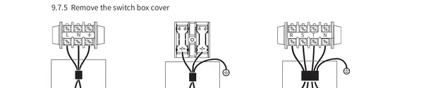
Protection: fit a high-speed earth-leakage breaker rated 30 mA (<0.1 s) and a fuse/breaker on the supply line. Use 3-core shielded cable of at least 60245 IEC 57 quality. Take the cable size and breaker/fuse rating from the unit nameplate and the electrical data in the installation manual (size wiring from MCA, fuse from MFA).
Signal & control terminals
Low-voltage controls land on CON1, CN1–CN4 and U19. The most relevant for a typical install:
| Terminal | Connects to | |
|---|---|---|
| CON1 ① | OFF1 / ON1 / N | SV1 3-way valve — DHW diverter |
| CON1 ②③ | OFF2/3 · ON2/3 · N | SV2 / SV3 3-way valves (e.g. Zone 2 mixing) |
| CON1 ④ | P_c / N | Pumpc — Zone 2 pump |
| CON1 ⑤ | P_o / N | Outside circulation pump / Zone 1 pump |
| CON1 ⑦ | P_d / N | DHW recirculation pump |
| CON1 ⑨ | AHS1 / AHS2 | Additional heat source |
| CON1 ⑬ | AC_L / AC_L1 / AC_HT | Room thermostat input (high voltage) |
| CN1 | CL / COM / HT | Room thermostat input (low voltage) |
| CN2 / CN3 | SG / EVU | Smart Grid / EVU signals |
| CN4 | — | Cascade communication (module sequence) |
| U19 ① | 12V·GND·L_A·L_B | Wired controller |
| U19 ② | 12V·GND·I_A·I_B | To outdoor unit |
| U19 ③ | H1 / H2 | RS485 Modbus (H1-B, H2-A) |
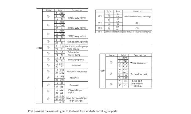
Control-signal types. Type 1 ports are dry contacts (no voltage). Type 2 ports carry 220 V: a load under 0.2 A can connect directly, but a load of 0.2 A or more needs an AC contactor.
03Basic settings
The core commissioning choices. Each opens from Menu › Installer Level › System Parameter.
Activate / deactivate hot water (DHW)
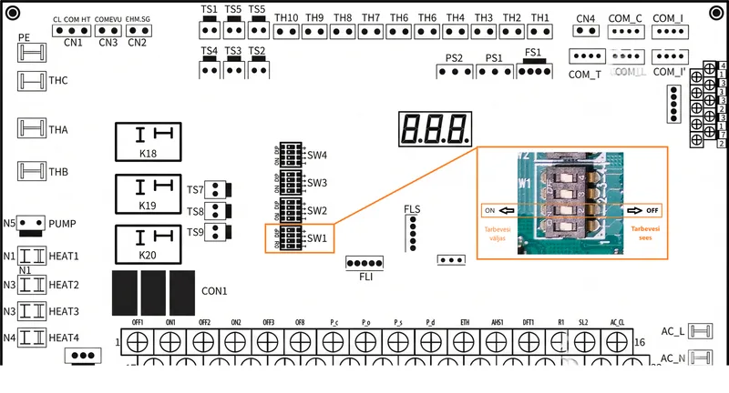
Whether the unit produces hot water at all is set by a DIP switch — SW1-2 — on the main control board inside the unit, not in the controller menu.
| SW1-2 | Result |
|---|---|
| OFF | DHW mode valid — hot water enabled; the DHW tile appears on the home page. |
| ON | DHW mode disabled — space heating / cooling only, no DHW tile. |
Switch off all power before changing any DIP switch. DHW also needs the DHW tank sensor (Tw) and the SV1 3-way valve wired (see Cable connections) before it will work.
Configure DHW temperatures (installer)
Open … › System Parameter › DHW MODE SET and set the start/target values and tank heater:
Tb = start delta below target · Tx = target tank temperature. Set TANK HEATER to Disable if no electric booster is fitted.
1-zone or 2-zone operation
The number of heating/cooling circuits is set in … › System Parameter › TEMP. TYPE SET with 01 ZONE TYPE. Set this first, then follow the matching block below.
If you use ONE zone
A single circuit fed by the main circulation pump (P_o). This is the typical setup.
Set ZONE TYPE = ONE. 02 SINGLE ZONE OPERATION sets fixed vs weather-curve target — see Weather compensation.
Wire the Zone 1 / main circulation pump to CON1 ⑤ (P_o).
Set the Zone 1 emitter type — see Emitter type per zone below.
Set how Zone 1 follows the temperature (fixed or weather curve) with 02 SINGLE ZONE OPERATION — see Weather compensation.
If you use TWO zones
Zone 1 (usually the high-temp / direct circuit) plus Zone 2 (usually a mixed low-temp circuit, e.g. underfloor) fed through a mixing valve.
Set ZONE TYPE = TWO. 03 DUAL ZONE OPERATION sets each zone's target type — see Weather compensation.
Wire the Zone 2 pump to CON1 ④ (P_c / Pumpc) and the Zone 2 mixing valve SV3 to CON1 ③ (OFF3 / ON3 / N).
Fit a Zone 2 water-temperature sensor (TZ2) and, if used, the Zone 2 room thermostat.
Set the emitter type for each zone — see Emitter type per zone below.
Set each zone's target type with 03 DUAL ZONE OPERATION — see Weather compensation.
Configure the mixing valve — see below.
Set the Zone 2 mixing valve (SV3)
Open … › System Parameter › MIXING VALVE SET. These tune how the SV3 motorised valve opens/closes to hold the Zone 2 water temperature:
01 TZ2 = enable the Zone 2 temperature sensor (must be Enable for mixed Zone 2). t_SV3_ON/OFF = valve drive time per step; dT_SV3_ON/OFF = temperature deviation that triggers the valve to open/close.
Leave the timing/deviation values at their defaults unless Zone 2 over- or under-shoots its target; then adjust in small steps.
Emitter type per zone — FCU / radiator / floor
Tell the controller what each zone feeds so it manages temperatures correctly. Set it separately for heating and (if used) cooling.
Heating
Open … › System Parameter › HEATING MODE SET:
Cooling (if the system cools)
Open … › System Parameter › COOLING MODE SET:
Floor cooling (value 2) is only allowed on a zone driven by the wired controller, not a room thermostat.
Activate / deactivate weather compensation
With weather compensation on, the controller sets the target water temperature from the outdoor air temperature using a climate curve, instead of a fixed setpoint — warmer outside means cooler water, which saves energy. Turning it on is two steps: enable it per zone (Step 1), then choose the curve (Step 2).
Step 1 — enable it per zone
In … › System Parameter › TEMP. TYPE SET, set the operation value. A "fixed" value means weather compensation is OFF; any "curve" value turns it ON.
One zone (ZONE TYPE = ONE)
Set 02 SINGLE ZONE OPERATION:
Two zones (ZONE TYPE = TWO)
Set 03 DUAL ZONE OPERATION — this picks the target type for Zone 1 and Zone 2 together:
| Value | Zone 1 | Zone 2 | Comp. |
|---|---|---|---|
| 0 | fixed water | fixed water | OFF |
| 1 | fixed water | weather curve | Zone 2 |
| 3 | fixed water | room + weather curve | Zone 2 |
| 4 | weather curve | fixed water | Zone 1 |
| 5 | weather curve | weather curve | Both |
| 7 | weather curve | room + weather curve | Both |
To deactivate weather compensation, set the operation value back to a fixed-water-temp option (single zone → 0; two zones → 0), and the unit follows the manual setpoint again.
Step 2 — choose the curve
Open … › System Parameter › WEATHER TEMPERATURE CURVE SET and set the curve number for each zone and mode:
A = Zone 1, B = Zone 2 · H = heating, C = cooling. So 03 A-H = Zone 1 heating, 07 B-H = Zone 2 heating.
Reading the curve parameters
Each zone/mode has both a LOW and a HIGH curve slot; the controller automatically uses the one that matches the emitter type you set for that zone:
| Slot | Used when emitter is… | Produces |
|---|---|---|
| LOW temp curve | Floor heating (low-temp) | Lower water temperatures |
| HIGH temp curve | Radiator or FCU (high-temp) | Higher water temperatures |
So for an underfloor zone, the LOW curve is what takes effect; for radiators or fan coils, the HIGH curve. There are 8 preset curves per slot (1–8): a higher number gives a hotter target at the same outdoor temperature.
Individual (custom) curve — the 9th curve
If none of the 8 presets fit the building, select curve number 9 — "Custom curve". This lets you define your own outdoor-temperature → water-temperature relationship for that zone and mode, rather than using a preset.
The custom curve points are entered on the controller's User Control › Weather Compensation page (also reachable to the end user). While any weather-compensation curve is active, the desired water temperature can't be set directly on the home page — it follows the curve.
04First power-up checklist
Work top to bottom. Don't apply power until every item under "before power-up" is confirmed.
Before power-up
The main switch must be OFF while you check the switch box. Verify each item below before switching on the circuit breaker.
Field wiring between supply panel, unit and valves matches the supplied wiring diagram, with the right wire size and a correctly rated breaker / RCD (30 mA, <0.1 s).
Earth is connected; earth-leakage protection is fitted.
Internal wiring — visually check for loose connections or damaged components.
Water circuit is filled, air purged, and pressure is 0.10–0.20 MPa (≈1–2 bar cold).
Shut-off valves are fully open.
Stop valves (gas/liquid) are open.
DIP switches (SW1–SW4) on the main board match the installation — set these with the power OFF.
Power up & configure
- Switch on the supply. The controller lights up; the indicator LED is steady-on when the unit is off.
- Enter
Installer Level(passcode1212) →System Parameter. - Set ZONE TYPE, then the emitter type per zone, weather compensation, and confirm DHW — as in Section 03.
Initial run
For a fresh concrete/screed floor, raise water temperature gradually — rapid heating can crack the slab. Follow the screed contractor's drying schedule.
Verify correct operation in each mode the system uses (heating, DHW, cooling).
Close all panels and refit the cover before leaving the unit running.
During the first running period the input power can be higher than stated and consumption less stable while the compressor settles — this is normal.
05Common error codes
Codes show on the controller when a protection trips. Reset by turning the unit OFF and back ON; if the same code returns, diagnose before resetting again. The full list is in the service manual.
Protection codes (P)
| Code | Meaning | First checks |
|---|---|---|
| P01 | Water-flow protection | Open closed valves, clean Y-filter, purge air, check flow switch. |
| P02 | High-pressure protection | Low water flow, HP switch fault, refrigerant blockage or EXV locked. |
| P03 | Low-pressure protection | Refrigerant shortage/leak, system blocked, running out of range. |
| P04 | Condenser over-temp | Poor outdoor airflow, dirty condenser, T3 sensor fault. |
| P05 | Discharge-temp protection | Refrigerant shortage or discharge sensor fault. |
| P06 | Anti-freeze (leaving water) | Low flow, blocked exchanger / filter, load too low. |
| P11/P12 | DC fan 1 / 2 failure | Fan stuck or main board fault. |
| P14 | Refrigerant leakage | Leak in system, leak sensor fault, or PCB fault. |
| P21 | DC pump abnormal | Pump blocked, low water, or board fault. |
Error codes (E)
| Code | Meaning | First checks |
|---|---|---|
| E01 | Controller communication error | Check cable/plug between controller and unit (U19); replace controller, then board. |
| E02 | TP discharge sensor fault | Check sensor wiring; swap with a known-good sensor; replace board. |
| E03–E09 | Temp-sensor faults (T3, T4, T5, etc.) | Same sequence as E02 — wiring, then sensor, then board. |
| E15–E36 | Drive / inverter module errors | Inverter or compressor side — refer to the service manual. |
Always switch off the main switch before inspecting the switch box. If a safety device tripped, find the cause first — safety devices must never be bridged or replaced with a different rating.